
Patrick Grabowski remains Chief Executive Officer of LISEGA SE
1. January 2026LISEGA SE has confirmed Patrick Grabowski as Chief Executive Officer (CEO). Since taking over on an interim basis in March ...
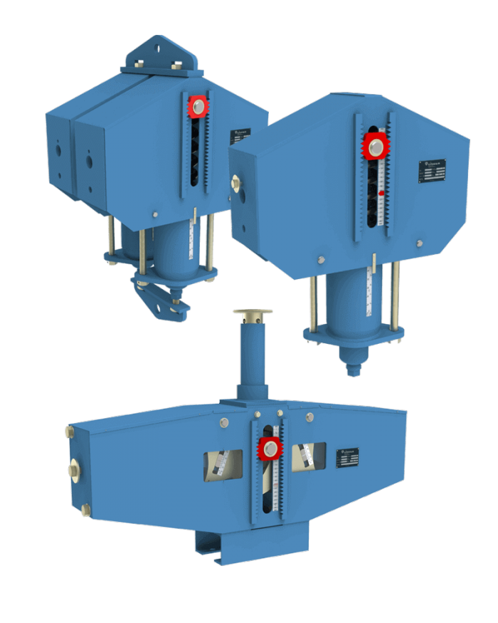
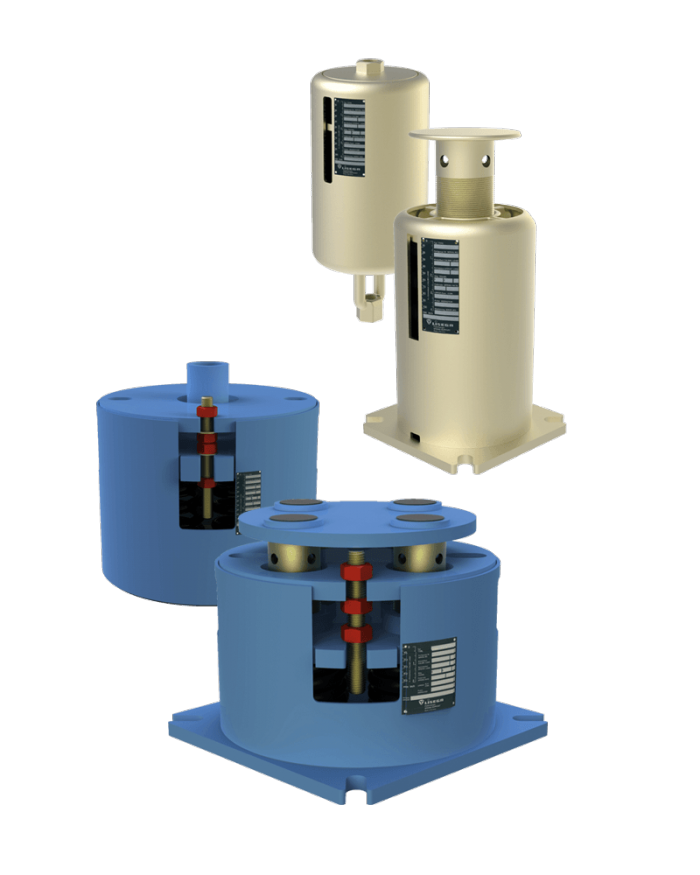
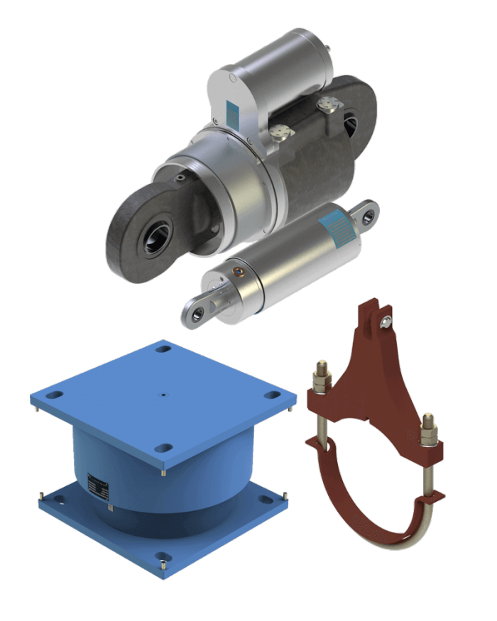
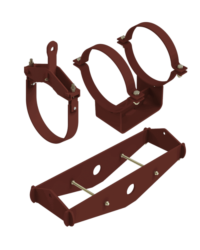
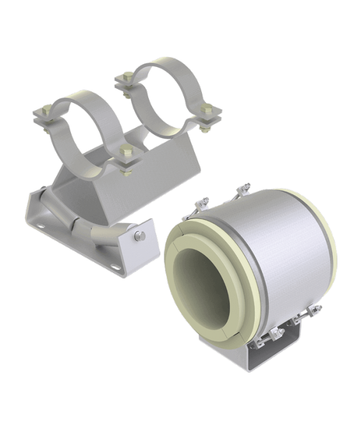
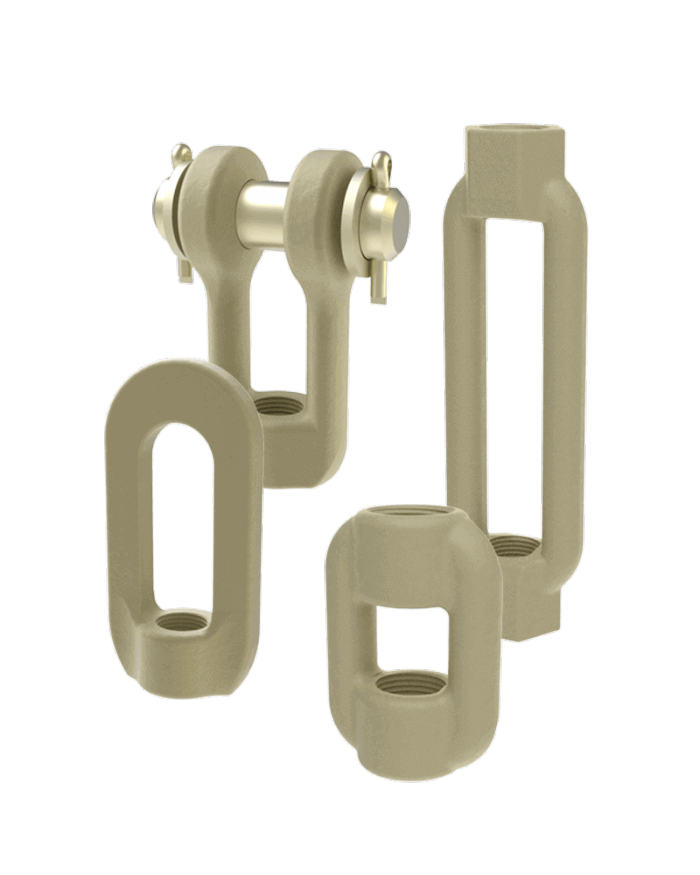
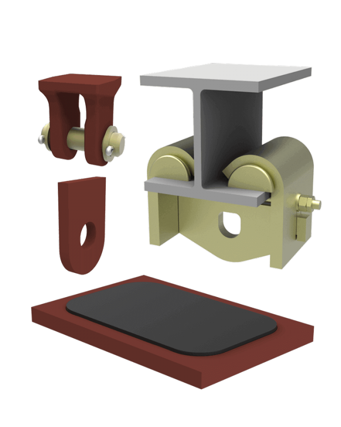
to full articleThe LISEGA group of companies is the world’s leading specialist for industrial pipe support systems. With tens of thousands of items, the LISEGA product range is the world’s most comprehensive modular pipe support program, offering technical solutions for all typical industrial applications.
A complete product portfolio with tens of thousands of components covers all support situations, operational loads, temperatures and travel ranges normally experienced in piping systems in industrial plant construction. LISEGA’s modular system provides the corresponding basis. All components have a connection compatible with their load groups.
LISEGA SE has confirmed Patrick Grabowski as Chief Executive Officer (CEO). Since taking over on an interim basis in March ...
to full article
CSR: Our course toward a responsible future Our new Corporate Social Responsibility (CSR) brochure documents how responsibility for the world ...
to full article
We are pleased to announce the redesign of our brand image, which reflects our commitment to quality, reliability, and technical innovations. For over ...
to full article